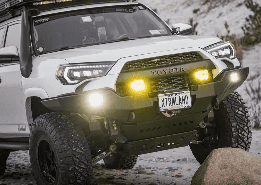
Overland Vehicles

A custom CAD design service translates a rough idea into a manufacturable plan. It starts with requirements gathering, use cases, and constraints like payload, envelope, temperature, vibration, or regulatory needs. From that, the designer produces 3D models that express geometry, fit, and function with parametric relationships, so dimensions can update predictably when a constraint changes.
Beyond the 3D surface, the service produces drawings that guide fabrication and inspection. Drawings usually include views, sections, exploded details, tolerances, geometric dimensioning and tolerancing per common standards, material specs, surface finishes, and hardware lists. Clear drawings reduce interpretation errors, speed quoting, and protect intent when multiple vendors are involved.
Deliverables typically include neutral 3D formats for interoperability, such as STEP for machining and parasolid workflows, plus DXF or DWG profiles for laser, plasma, and waterjet. For sheet metal, bend tables and flat patterns are paired with K factor assumptions to match the target press brake. For assemblies, a bill of materials clarifies part numbers, fasteners, coatings, and purchased items.
Parametric modeling links dimensions and features through equations and constraints. This makes families of parts easy to manage, supports late-stage tweaks, and preserves intended clearances. Done well, parametric structure avoids broken feature trees while supporting rapid iteration.
A design is only as good as its tolerance stack. Realistic hole clearances, weld gaps, bend radii, and corner reliefs keep parts buildable. Notes for tab and slot, hem details, grain direction, and coating thickness reduce surprises when the first article arrives.
Exploded views and section cuts help non engineers understand tradeoffs. Renders establish material palette and finish expectations. Simple animations can show motion envelopes, latch action, or service access, which guides feedback before cutting metal.
The workflow begins with discovery. A good intake defines the problem, success criteria, constraints, and interfaces. Reference parts and measurement data are gathered early, often supported by calipers, CMM scans, or photo-based measurement to capture real world variance.
Modeling follows a plan of features that matches the manufacturing route. For CNC parts, designers consider tool reach, workholding, and chip evacuation. For sheet metal, bend order, minimum flange lengths, and nested flat layouts are anticipated. For weldments, joint prep and distortion risks are addressed up front with gussets, stitch patterns, or fixtures.
Prototyping validates assumptions. 3D printed fixtures can probe fit in minutes. Trial laser cuts confirm bend allowances and hole sizing for hardware. If the assembly is load bearing, a quick FEA pass can flag stress risers, while hand calc checks keep the model honest. Lessons learned feed a revision that locks geometry for production.
Clarifying payload, fatigue cycles, thermal limits, and mounting options narrows the design space. When budget and timeline are set early, the design can target readily available stock and common processes.
Equations and reference geometry capture rules, not just shapes. Controlled variables enable size range exploration without redrawing, saving time and reducing errors.
Test coupons and quick prints catch clearance issues before they become scrap. Even simple go no go gauges can prevent a failed run.
Professional drawings typically follow familiar conventions for clarity. Title blocks store part number, revision, scale, units, and material. GD and T is applied where function demands control of flatness, position, or concentricity. Default tolerances can reference standard practice while critical features get explicit limits. When vendor capabilities vary, tolerances align with the chosen shop to balance cost and precision.
File packages are built to travel well. STEP files for solids, DXF for profiles, PDF drawings for clarity, and native files if collaboration warrants it. PDM or a shared repository protects version integrity, so purchasing and the shop floor always pull the same revision. Change logs record what moved and why, which simplifies audits and maintenance later.
Quality control links back to the model and drawing. Inspection notes, measurement points, and datum schemes drive consistent checks. For assemblies, fit checks and torque specs ensure repeatability. When updates happen, the CAD database remains the single source of truth.
This same rigor pays off in vehicle and overland applications where space is tight and loads vary. CAD driven brackets, battery trays, roof modules, and interior systems benefit from smart packaging and documented mounting points. If the goal is a dependable trail build, that discipline starts at the model. For an example of how design supports real world upgrades, explore our overland rigs. When a project needs tailored mounts, racks, or interior structure, a focused custom overland upfit ensures the CAD matches fabrication realities. Curious about our approach and process culture? Visit Why choose OZK Customs.
From concept to files and drawings, the path is straightforward when the fundamentals are respected. If you are ready to turn your idea into a build ready model, share a few details below and we will map the scope, deliverables, and schedule that fit your project. Whether it is a single bracket or a complete interior system, we will model it clearly, document it properly, and prepare it for the shop floor.
Ready to see your idea modeled, validated, and prepared for fabrication? Submit the form and our team will outline scope, timelines, and deliverables for your project. We turn concepts into build-ready CAD and drawings that move straight to production.
ADDRESS:
6159 E Huntsville Rd, Fayetteville, AR 72701
PHONE:
(479) 326-9200
EMAIL:
info@ozkvans.com